What is ARINC?
The ARINC Corporation is a privately held organization that stands for Aeronautical Radio, Inc. It is, however, a firm that collaborates with the Federal Aviation Administration (FAA) and the Federal Communications Commission (FCC) to develop aviation communication and navigation standards.
As a result, the boundary between business and government might be a little blurry at times. The services provided by ARINC go beyond communications. ARINC collaborated with the US military to develop military VHF radio communications in the 1940s.
“ARINC was once based in Annapolis, Maryland, with regional offices in London (founded in 1999 to service Europe, the Middle East, and Africa) and Singapore (founded in 2003 to serve the Asia Pacific). ARINC employs approximately 3,200 people in over 120 sites across the world.
The $1.4 billion acquisition of ARINC by Rockwell Collins, a Cedar Rapids, Iowa-based aviation and defense electronics firm, was finalized on December 23, 2013, and from November 2018, it is operating as part of Collins Aerospace.
It seemed reasonable to have a separate firm handle everyday communications so that each company didn’t have to set up its ground communications network. ARINC’s services are employed by airports, defense, healthcare, security, and other transportation businesses such as railroads”
In addition to its substantial activity in aviation. ARINC has taken the lead in establishing avionics equipment specifications and standards. Specifications and standards are developed by industry-wide groups.
The FAA’s Next Generation Air Transportation System project and Europe’s Single European Sky ATM Research (SESAR) effort both rely heavily on avionics.
Avionics refers to the electronic systems found on planes, satellites, and spacecraft. Communications, navigation, the display and control of numerous systems, and the hundreds of systems installed to aircraft to perform particular duties are all aspects of avionic systems.
These might be as basic as a searchlight for a police helicopter or as complex as an airborne early warning platform’s tactical system.
ARINC is focused on two primary goals:
- Aviation and tourism sector communications and information processing services.
- For government and industry, system engineering, development, and integration.
ARINC also created the specifications for the trays and boxes used in airplanes to house standard line-replaceable equipment (such as radios). As a result, electronics may be quickly replaced without the use of complicated fasteners or test equipment.
History of ARINC
Aeronautical Radio, Incorporated (ARINC) is a major corporation that develops and runs technologies and services to assure the aviation and travel sectors’ efficiency, operation, and performance.
It was founded in 1929 by four major airlines to offer a single radio communications licensee and coordinator outside of the government.
All airlines and aircraft can use ARINC’s services, but only airlines and aviation-related firms can be shareholders. ARINC was owned by airlines and other aviation-related firms for most of its existence, until it was sold to The Carlyle Group in October 2007.
Aircraft Communications Addressing and Reporting Systems (ACARS) were invented by ARINC and American Airlines in the 1970s.
This technology allows airplanes and different ground resources to communicate directly.
ACARS is now an industry standard for tracking and recording aircraft and aircrew flight and block time and cockpit crew to dispatcher digital communications, weather, weight and balance, real-time performance statistics, and a variety of other important and incidental flight data.
Through its ARINC Engineering Services division, ARINC has grown its aerospace and defense sector.
The ARINC Engineering Services division was divided into Commercial Aerospace and Defense Services when the firm was sold to Rockwell Collins.
After that, Booz Allen Hamilton bought the Defense Services division, which remained part of the Carlyle group.
Concerns about conflict of interest arose from the selling of a Standards Development Organization (SDP) to a corporate sponsor, which led to the transfer of the ARINC Industry Activities (IA) Division to SAE International in January 2014.
It is currently known as SAE Industry Technologies Consortia (SAE ITC). Visit sae/works/doc for a detailed description and documentation listings of various ARINC Industry activities.
What does ARINC Do?
Mechanical flying was simple: pilots pressed a joystick or stepped on a pedal, and a system of rods, wires, and pulleys slid, twisted, and turned to control the aircraft’s motions. Today’s fly-by-wire planes are a little more complicated.
To monitor fuel levels, navigate the skies, identify weather patterns, and do everything else connected with effective flight, various electrical devices must be able to function together.
The Airlines Electronic Engineering Committee (AEEC) creates standards, which ARINC copywrites and publishes. The AEEC is a global standards body made up of major airline companies, avionics manufacturers, and ARINC members.
The AEEC establishes standards for avionics equipment and systems, as well as industry-defined requirements for form, fit, and function consistency among diverse manufacturers’ products.
People and companies alike need to stay connected in today’s environment. That is especially true in aviation, where airlines, crew members, airports, ground handlers, air traffic controllers, and don’t forget passengers all rely on a connection to guarantee smooth operations and on-time arrivals.
The various activities and services offered by ARINC are discussed below as gathered from various resources and some papers from aviation committee archives.
ARINC services
- ACARS is a digital datalink system that uses radio or satellite to send brief, relatively basic communications between aircraft and ground stations
- AviNet Global Data Network (previously known as ARINC Data Network Service) is a global data network that connects people across the world (ADNS)
- Domestic Voice Service (Air/Ground)
- International Voice Service (Air/Ground)
- Airport Remote Radio Access System (ARRAS)
- AirDB – Airport Operational Database Base (AODB)
- AirPlan by ARINC – Resource Management System (RMS)
- Passengers are validated at security checkpoints using VeriPax – Passenger Reconciliation System (PRS)
- Centralized Flight Management Computer Waypoint Reporting System (CFRS)
- Air Traffic Control and Landing Systems (ATCALS), as well as Satellite Navigation (SATNAV)
- In-flight Broadband — in collaboration with SwiftBroadband, provides passengers and staff with the in-flight connection.
- Passenger data transmission and the Advanced Passenger Information System are also part of the AviSec system.
- Advanced Information Management (AIM) User Interface
- Cybersecurity for Critical Infrastructure

NOTE: ACARS description.

NOTE: In-flight internet example. From the Lufthansa article.
ARINC Standards & Protocols
The ARINC Industry Activities secretariat publishes the technical standards established by the AEEC, AMC, and FSEMC as ARINC Standards. More than 10,000 air transport and business aircraft across the globe use ARINC Standards to specify avionics, cabin systems, protocols, and interfaces.
Standardization and ARINC Industry Activities
- AEEC (Airlines Electronic Engineering Committee): Develop the ARINC Standards.
- AMC (Avionics Maintenance Conference): Organize the annual Avionics Maintenance Conference.
- FSEMC (Flight Simulator Engineering & Maintenance Conference): Organize the annual FSEMC conference.
The AEEC standards are published by ARINC in three different formats:
ARINC Characteristics:
The structure, fit, and function of avionics equipment are defined by characteristics. These documents are unique to the device and describe how it will function.
The ARINC 500 Series of Characteristics describes older analog avionics equipment, whereas the ARINC 700 Series papers are more recent and are generally digital copies of the analog specifications.
The 400 Series papers include general design and support information for the 500 Series avionics equipment.
The 600 Series papers are generic design and support documentation for avionics equipment in the 700 Series.
ARINC Specifications:
As discussed in an article on aim-online, the specification defines:
- Avionics equipment packing and installation.
- Communication protocols for data.
- High-level programming languages.
ARINC Reports:
For airlines, reports give basic information as well as best practice standards. The majority of reports deal with maintenance and support processes.
Aircraft Generation ARINC Standards:

The Airlines Electronic Engineering Committee (AEEC) develops the ARINC Standards, including contributions from aviation vendors such as Collins Aerospace and GE Aviation in support of its airline customers. The condensed version of the list can be found listed on Wikipedia/arinc_standards.
ARINC 429
The ARINC 429 defines basic requirements for the transmission of digital data between commercial avionics systems. For ease of design implementation and data communications, signal levels, timing, and protocol characteristics are specified. ARINC 429 is designed to provide commercial aircraft Line Replaceable Units (LRUs). As in a layman’s term, the ARINC protocol is designed to support communication in the Local Area Network (LAN) of the avionics.
ARINC 429 standards is also known as the Mark 33 Digital Information Transfer System (DITS) bus. Although used mostly in the field of avionics, these buses are also used in the field of ground vehicles, weapons systems, and other commercial and military equipment.
The word structure, the electrical component characteristics, and the protocol needed for the requirement of successful communication is defined in the specifications. The Simplex, twisted shielded pair data bus standard Mark 33 DITS bus is used by ARINC-429. Both the hardware and data formats needed for bus transmission are specified by ARINC.
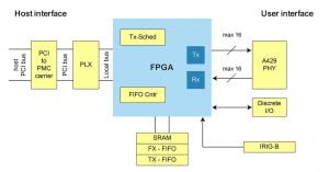
A single connected transmitter or source consists of the hardware connected to from 1-20 receivers or sinks on one twisted wire pair. Data can only be transmitted in one direction (unidirectional connection), for bi-directional communication, requires two channels or buses.
In a star or bus-drop topology, the modules, line replaceable units or LRUs, are most commonly configured. Multiple transmitters and receivers communicating on separate buses can be present in each LRU. Figure 1 shows the preferred connection topologies for the data bus. This simple architecture provides a highly efficient transfer of data, almost node-to-node connectivity.
A transmitter can only talk to some bus receivers, up to 20 on a single wire pair, with each receiver monitoring the related data continuously, but not accepting data reception. When large quantities of data have been transmitted, a transmitter can require acknowledgment from a receiver.
As compared to a hard-wired handshake, this handshaking is done using a specific word style. Two twisted pairs comprising two channels are sufficient to carry information back and forth, one for each direction when this two-way communication format is needed.
The transmission of the LRU source consists of 32-bit words containing a portion of 24-bit data containing the actual data and an 8-bit label describing the data itself. LRUs do not have an address assigned by ARINC 429, but rather equipment ID numbers that allow device management and file transfer of equipment to be grouped into systems.
A null or zero voltage of at least 4 bits distinguishes sequential words. By using this null interval between words, a separate clock signal is unnecessary. That’s why this signal is known as a self-clocking signal.
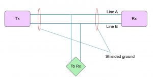
Transmission rates can be either at a low speed of 12.5 kHz or a high speed of 100 kHz. For the transfer bus media, a 78 x shielded twisted pair cable is used. The shield needs to be grounded at either end and all junctions along the bus. The transmitting source output impedance should be 75Ω ± 5Ω equally split between Line A and Line B.
This balanced output should closely match the cable impedance. There must be a minimum effective input impedance of 8k x for the receiving sink.
There is no definition of the maximum length, as it depends on the number of sink receivers, the drain of the sink, and the source power. Most systems are designed for less than 150 feet, but if conditions permit, they can be extended up to 300 feet and beyond. Fig 2 shows the cable attributes for the ARINC 429.
Word Format
ARINC 429 assigns the first 8 bits as the wordmark, bits 9 and 10 are the Source-Destination Indicator (SDI), bits 11 through to 28 provide data information, bits 29 through to 31 are the Sign-Status Matrix (SSM) and bit 32 is a Parity Bit.
ARINC 429 data words are 32-bit words made up of five primary fields:
- Parity – 1-bit: ARINC uses odd parity as an error check to ensure precise data reception. The number of transmitted Logic 1s in each word is odd, with bit 32 set or cleared to get the odd count. ARINC 429 specifies no method of error correction, only error detection.
- Sign/Status Matrix (SSM) – 2-bits: Depending on the word Label, which indicates the form of data is being transmitted, the SSM field may provide different information. This field can be used to view the word information’s sign or location or to report the operating status of the source system and is dependent on the data type.
ARINC


- Data – 19-bits: ARINC 429 identifies bits 11-29 as those which contain the data information for the word. The data pieces, indeed the entire word of ARINC 429, can be formatted very flexibly. When the data words are transmitted on the ARINC bus, the mark is transmitted first, MSB first, followed by the remainder of the bit field, LSB first.
- Source/Destination Identifier (SDI) – 2-bits: Bits 9-10 are used by the Source/Destination Identifier-SDI-and are optional under the ARINC 429 specification. To determine the receiver, the data intended for the SDI may be used to identify the source that transmits the data or by several receivers. Instead of using them as an SDI sector, bits 9-10 can be used for higher resolution data. The SDI is interpreted as an extension to the term Label when used as an identifier.
- Label – 8-bits: The mark is used to define the word’s data type (BNR, BCD, Discrete, etc.) and may contain instructional or data reporting information. Labels can be further refined by using the first 3-bits of the data field, Bits 11-13, as an Equipment Identifier to identify the bus transmission source. Equipment IDs are expressed in hexadecimal form as values. In an ARINC transmission, the label is always sent first and is a necessary sector, as is the parity bit. Labels are first transmitted by MSB, followed by the remainder of the ARINC phrase, first transmitted by LSB.

Data Types specified in ARINC 429:
- Binary Coded Decimal (BCD): The advantage of the Binary Coded Decimal technique is that each decimal digit is represented in the same way as Hexadecimal by a group of 4 binary digits/bits. So, for 10 decimal digits, we need a four-bit binary code (0-to-9). For displaying every decimal digit, the BCD format uses four bits of the data field. To provide 5 binary values, up to 5 sub-fields can be used, with only 3 data field bits in the most significant sub-field. Bits 27-29 are padded with zeros if the Most Significant Digit is greater than 7 and the second sub-field becomes the Most Significant Digit, enabling the representation of 4 binary values instead of 5. The SSM field represents the sign of the data.
- Binary Number Representation (BNR): The fractional complement of the binary two. BNR coding stores information as a binary number. The sign of the data is stated with the bit 29, and a 1 indicates a negative number. MSB of the data is given by bit 28.
- Discrete Data: It can be a combination of BNR, BCD, or ISO #5 bits. By setting or clearing predefined bits in the word data field, Pass/Fail, Activated/Non-Activated, and True/False conditions relating to device or subsystem operational activity can be described.
- Maintenance Data / Acknowledge: Maintenance details and acknowledgment means duplex or two-way communication between source and sink. For the LRU to send and receive data, two ARINC channels are required, because ARINC 429 provides for single-way simplex transmission only. Maintenance messages typically involve the exchange of a series of messages and mostly use a bit-oriented protocol, such as the Williamsburg/Buckhorn protocol.
- Williamsburg/Buckhorn Protocol: A bit-oriented protocol used to transfer files on the ARINC Databus. If we require to transmit data more than 21 bits, file transfer protocol becomes a necessary and important factor. Source and sink units need to first create a handshake when initializing a file transfer with the bit-oriented protocol to decide a standard protocol that can be used by both the transmitter and the receiver. A Word Send Request (RTS) containing a destination code and word count is transmitted. To ensure accuracy, the receiver responds with a Clear to Send word (CTS), re-transmitting back the destination and word count information. Upon verified receipt of the CTS files, the file transfer begins with the source.
Extending to other ARINC standards
High reliability and small data rates at the cost of wire weight are provided by the unidirectional ARINC 429 network. Military aircraft typically use a high-speed, bi-directional protocol specified in the Military Specifications of MIL-STD-1553. A newer system is installed on the 777 listed as ARINC 629 by Boeing, and some aircraft are using alternative systems to try and reduce the necessary wire weight and exchange data at a higher rate than is possible with ARINC 429.
Bell Helicopters, Boeing 727, 737, 747, 757, and 767, and McDonnell Douglas MD-11 are equipped with ARINC 429, the majority of which are commercial transports, such as aircraft A310/A320 and A330/A340.
ARINC 629
ARINC 629 was launched in May 1995 and is currently being used on aircraft such as the Boeing 777, Airbus A330, and A340. The specification is based upon the Digital Autonomous Terminal Access Communications (DATAC) development work of Boeing Commercial Aircraft.
Related Read: ARINC 629 Specifications
This ARINC bus is a true data bus in that the bus functions as a multiple-source, multiple sink system. That is, every terminal on the data bus will send data to and receive data from every other terminal. This enables the sharing of data between units in the avionics system to be much more flexible. It supports a 2 Mbps data rate.
ARINC 629 protocol is a time-based, collision-avoidance protocol in which a fixed time slot is allotted to each terminal to access the bus and transfer data to the bus. By using multiple control timers embedded in the bus interfaces, each terminal will autonomously determine when the appropriate time slot is available and transmit the necessary data. (20-bit word format) The first three bits are linked to word time synchronization.
The next 16 bits are the data information, and a bit of parity is the final bit. The data terms, which include a variety of formats, include general formats, system status, feature status, parameter validity, and binary and discrete data words, depending on the word function. The ARINC 629 data bus cable consists of an unshielded twisted pair of wires. The wires are #20 AWG and are bonded together continuously along their length. The cables can be up to 100 meters long and do not have any specifications for field splicing.
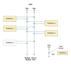
ARINC 629 is defined for both voltage and current modes of operation. One of the appealing features of ARINC 629 is the specification of the ARINC 629 fiber optic interface for data transmitted in groups called messages. Messages consist of word strings; up to 31-word strings can be found in a letter. The word strings start with up to 256 words of data followed by a name.
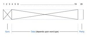
Label Word:

Data Word:

Data Types supported:
- Binary Number Representation (BNR): BNR coding stores data as a binary number. The BNR is the most efficient in terms of bus power and should typically be used. With Bit 19, the BNR Numeric Data Word Sign should be encoded. In data bit 19, negative BNR numbers are encoded as the two complements of positive values by the negative sign denoted as logic 1.
- Binary Code Decimal (BCD): Numerical Subset of ISO Alphabet No 5
- Alphanumeric Data: Should be coded per ISO Code #5
- Discrete Data: Should be transmitted in dedicated discrete words
Timers:
Because of the absence of the actual bus controller, three timers allow each RT to transmit when it should and avoid any data collision on the bus.
- Transmit Interval (Global parameter and longest of the three): If the RT has been transmitted, it must wait (at least) for the time specified by the TI to be able to transmit it again. It varies from 0.5005625 to 64,0005625 milliseconds, which corresponds to 1,000+ to 128,000+ bit times at the 2Mbps transmission rate. Seven bits can describe the binary value (BV) of the TI. Divided by 2 plus 0.5005625, the decimal value (BV at base 10) is the TI length of time in milliseconds. The TI begins when the RT starts transmitting.
- Synchronization Gap (Second longest): SG must have a binary value of 16, 32, 64, or 127 and must be chosen to be longer than TG. These values are equivalent to 17.7 μs, 33.7 μs, 65.7 μs, and 127.7 μs, respectively. The SG timers begin when a transmission stops (i.e. when the bus is quiet). If transmission occurs on the bus before SG has expired, SG is reset. When the SG expires, if a transmission happens on the bus, the SG is not reset. As its RT begins transmitting, the SG will be reset.
- Terminal Gap: Each RT is specific to the terminal gap. A unique number N, from 1 to 125, should be allocated to RTs. Multiple RTs should not bear the same N number. N + 1.6875 is the TG length of time in microseconds.
Protocol Aspects:
The key advantages of a multi-transmitter data bus include the ability to use fewer wires to pass more information at higher speeds between LRUs. Typically, they are more robust and have an architecture throughout the development phase that is more conducive to integrating complex systems.
These features translate into an improved economy and increased power for commercial aircraft customers. ARINC 629 couplers and data bus assemblies are placed together in panels in modern aircraft. During repairs, this enables faster access. The majority of coupler panels are covered; this also provides the couplers and bus cable assembly with protection from physical damage. Of the 11 data buses, nine are all couplers and the entire assembly of the data bus is entirely contained within a panel.
The various protocol features of ARINC 629 are compiled in the table below:

Two independent media access level protocols are defined in the 629 standard for communications through a common, multiple access database. Both are referred to as the basic protocol and the combined protocol; the key difference is the way bus arbitration happens. Aah, so now this makes you curious enough to dive into the world of avionics and how different components communicate inside those big and heavy aircraft. Also, it raises questions in your colossal mind.
ARINC 818
For advances of the 21st century, greater bandwidth and flexibility are required. The challenge is how to satisfy ever-expanding bandwidth and resolution requirements while retaining the versatility required to manage almost any video format. ARINC 818-2 is now being worked on with hundreds of planes and upgrades. This version now specifies 28 Gb/s speeds, allowing it to expand. For high-speed avionics systems, the ARINC 818 has become the real standard.
ARINC 818 is the encoded 8B/10B point-to-point protocol for video and data serial transmission. The Protocol is packaged, video-centered, and versatile, allowing multiple video streams multiplexing on one single link.
Even before its introduction, ARINC 818 has already been adopted by two major aerospace programs, the Boeing 787 and the Airbus A400M.
In the aircraft, a growing amount of information is given in the form of photographs, which passes through a complex video system before reaching the display in the cockpit and crew. Infrared and other wavelength sensors, optical cameras, radars, flight recorders, map/chart systems, synthetic sights, image integration systems, multifunctional head-up, and heads-down displays, video concentrations, or other subsystems are among the video systems available.

Systems Video is used for taxi and departure assistance, cargo loading, navigation, target tracking, collision prevention, and other essential features. ARINC 818 builds on the protocol of the Audio Fiber Channel (FC-AV as specified by ANSI INCITS 356-2002), which is commonly used on the F18 and C130AMP video systems. Although FC-AV has been used on various systems, each implementation has been specific. ARINC 818 offers an opportunity to standardize high-speed video systems.
ARINC 818 Specification
Bandwidth:
The fiber-channel protocol offered link rates of 1.0625, 2.125, 4.25, and 8.5 gigabits per second (Gbps) at the time ARINC 818 was ratified.
To meet market demand, link rates of 14.025 and 28.05 Gbps have since been made available. Even faster speeds are in the works.
ARINC 818-2 introduced rates of 5.0, 6.375 (FC 6x), 12.75 (FC 12x), 14.025 (FC 16x), 21.0375 (FC 24x), and 28.05 (FC 32x) Gb/s. To support the use of high-speed, bi-directional coax as a physical medium with power, the 6x, 12x, and 24x speeds were added.
The specification was expanded to include the option to define non-standard link rates for bi-directional return channels in situations when high-speed video communications are not necessary, like camera control.
Switching:
The point-to-point communication system known as the ARINC 818 protocol was developed. With the rising number of displays and/or ARINC 818 channels (10 or more) in many contemporary ARINC 818 implementations, switching has become more and more important. To ensure interoperability, the standard only defined a few stringent requirements.
Compression and Encryption:
ARINC 818 was originally designed to transmit uncompressed audio and video. Applications such as data-only apps, UAV/UAS with bandwidth-limited downlinks, and high-resolution sensors need the compression and encryption of communications.
The only information included in the ARINC 818 containers were flags indicating if the payload (data, video, or audio) was compressed, encrypted, or both.
According to the ARINC 818 philosophy of maximum flexibility, the implementation details are described in the Interface Control Document (ICD) for each project.
Channel Bonding:
Numerous parallel lines can get around FPGA bandwidth limitations thanks to ARINC 818-2. The video frame is transmitted via two or more channels after being divided into smaller pieces.
Each link must send a full ADVB frame with a header, and the ICD handles latency and skew between the links.
For instance, a WQXGA (2560 x 1600 pixels) image with 24-bit color depth at 60 Hz would require 737,280,000 B/s of bandwidth, according to one of those discussed on Aviation Today.
Using channel bonding, this image may be divided and delivered over two ARINC 818 4.25 Gbps lines. The ICD for that project specifies how the video should be re-split.
Data-only Links:
Data-only links are typically used as channels for command and control. A typical ARINC 818 link, for instance, may transmit the video stream from a camera or sensor.
The camera would get a data-only link that would be used to carry out operations like focus and white balance.
ARINC 818-2 is compatible with data-only links, which are frequently utilized in command-and-control channels, like those needed for bi-directional camera interfaces. For these, the ICD may define a non-standard rate or a regular link rate.
CRC Calculation:
One of the more challenging implementation issues with ARINC 818-1 was accurately determining the previous image CRC. It’s easy to make mistakes when doing complex CRC calculations. The specification now includes a detailed example of every stage of the Image CRC computation.
But Why prefer ARINC 818 IP for FPGA?
The Advanced Digital Video Bus (ADVB) is a fiber channel adaptation that adds capabilities for video and image transportation. Whereas a very wide range of industries and applications are supported in the FC-AV standard, ADVB focuses especially on the needs of avionics video. ADVB is made simpler through FC-AV, as it is unidirectional and doesn’t have a connection initialization, flow control, or other fiber channel exchange requirements such as port connections.
Although simplified, ADVB maintains Fibre Channel attributes that support vital mission video applications, such as high speed, high reliability, low latency, and flexibility. To merge images in real-time, such as symbology or cursors, all the imagery must be uncompressed while overlaying digital map images or real-time videos. The video needs considerable bandwidth without compression. Present ARINC 818 operations use up to 3Gbps with 8.5Gbps requirements. Since FC frame (packet) CRCs are used, ARINC 818 provides high data integrity. Packaged video enables simple data integration and generates multiple video streams for one connection link.
The video data created by the internal test pattern generator is received by the ARINC 818 IP transmitter block, which translates it into ADVB frames. The ADVB frames are transmitted via an FPGA transceiver attached to the SFP module. These ADVB frames are looped back to the Rx channel via the SFP module, where the video data is decoded by the ARINC 818-2 IP receiver block and presented on the HDMI monitor. The protocol has become the de facto standard for high-performance military and avionics video systems, and we use it to assist our customers to bring their visions to life with unrivaled FPGA design to deployment expertise.

NOTE: Relationship of container to video frames and ADVB frames.
Timing Classifications:
Appendix C of ARINC 818 sets out four Synchronization and Segmentation Classes (A-D) that describe asynchronous, frame, line, or pixel synchronous for timing constraints of the ADVB Link. The table below shows the different timing classifications for ARINC 818. The Interface Control Document (ICD) shall accompany the implementation of such ADVB projects in compliance with the ARINC 818 specification.
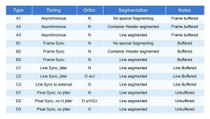
The ICD defines link parameters including link speed, image resolution, synchronization scheme, frame rate, and so on. Two systems of ARINC 818 will not be compatible if they aren’t built on the same ICD component. Generally, there will be an ICD associated with a military program or commercial avionics development.
Industries Served by ARINC
In the field of communications and systems integration, ARINC is a leading organization and majorly working in aircraft communication protocols. Customers in commercial aviation, US defense, and government rely on the company’s communications equipment, IT knowledge, and technical know-how to keep their operations running smoothly. Airport security, air traffic management, aircraft, and satellite testing, modeling and simulation, network design, passenger and luggage processing, voice and data communications, and weather reporting are among the company’s many products and services.
ARINC now supports approximately 15,000 airplanes, 300 airlines, 150 airports, and 200 train systems, as well as more than half of North America’s nuclear power facilities and other critical infrastructure. The mentioned industries are referred to from and as described in one of the case study documents of The Carlyle Group.
- Aviation Solutions: The world’s leading provider of aviation air-to-ground data communications.
- ARINC Direct: With over 3,000 airplanes under subscription, it is the leading supplier.
- Airports: With almost 60% of all installed common-use self-service kiosks and a 35% market share for common use terminals, top vendors.
- Surface Transportation: With 50 percent of the installed base in North America, the company is the leading supplier of rail control centers.
- Security: Advanced security systems are installed in more than half of the nuclear power reactors in the United States.
- Aerospace: Expertise in advanced engineering and in-depth knowledge of key military aircraft platforms.
ARINC’s Challenges
An open system, in its most basic sense, is an architecture (design) whose specifications are available to the public. The fact that an open systems architecture’s specs aren’t proprietary should be emphasized. It is, of course, permissible to use both officially authorized standards and privately designed architectures whose specifications have been made public.
The typical avionics implementation technique is federated, which implies that each aircraft function is composed of a separate set of sensors, processing units, and actuators. In most cases, data is not shared between functions.
As a result, in the avionics bay of aircraft for which the avionics suite was developed in the twentieth century, all identifiable units or “boxes” with one specific function, such as an inertial navigation system, an auto-pilot, a flight management system, a breaking and anti-skid system, and so on, can be found.
The disadvantage of this type of technology is that each box serves a distinct purpose and requires custom hardware and software.
Due to a lack of technology reuse, each system is essentially built from the ground up. The hardware component, in particular, suffers from obsolescence. Another downside is that each unit carries the burden of environmental protection as well as inherent power dissipation difficulties, leading to increased weight and power consumption.
Furthermore, because federated systems are not interchangeable, the logistics implications of federated systems imply a very inefficient way of handling spare parts.
The architectures of today’s avionics systems have a high level of integration. Data from sensors is shared among different platforms. Modularity is also introduced to some extent, particularly at the hardware module level. In truth, it has been an avionics supplier’s choice to provide the aircraft integrator with a fully integrated modular avionics system.
The majority of avionics functions are usually performed by a core computer. Several modules, such as display modules, flight management modules, autopilot modules, and so on, can be found inside this core computer, each performing a specific function.
ARINC’s Growth Over the Years
Since the first electronic devices were used in planes, signaling and inter-system communication have been a hot topic in avionics. Simple sensory feedback and components such as radar and engines had to be coupled to cockpit controls at first. As time went on, more and more data-producing and data-consuming systems were introduced into avionics, eventually becoming critical for even the most basic tasks, such as steering and later fly-by-wire. ARINC 429 is still used in most active and retired aircraft series today. While it is well-known in the industry, it hasn’t been updated or expanded much since the late 1970s when the original specifications were written.
Finally, a modern avionics networking design should provide a high level of safety, redundancy, and security, as well as failsafe defaults.
The resulting infrastructure should be easy to maintain, adaptable, and provide a strong platform for software development. Unlike the Internet, avionics prioritizes safety over security and cost-cutting. Most modern networking standards, on the other hand, are primarily concerned with addressing typical PC-world security goals and only tangentially address safety concerns. Avionics is the science and technology of electronics applied to aeronautics and astronautics, as well as the electronic circuits and components of a spacecraft.
A new concept in avionics technology is integrated modular avionics (IMA) that became common in the last decade.
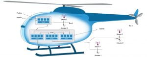
NOTE: Example of Integrated Modular Avionics System
Outside of the aerospace industry, Ethernet has been shown to be a reliable, cost-effective, expandable, and flexible technology. It cannot, however, provide key capabilities for high availability and reliability. As a result, it is not immediately applicable to avionics. While building on top of the previously reviled Ethernet standard 802.3, ARINC 664 provides modern-day transfer rates. Parts of the MIL-STD-1553 nomenclature and general setup are inherited by AFDX.
Subsystems are network-connected devices that convey data. End systems connect subsystems to the network. AFDX Interconnect is the name of the full-duplex network. ARINC 429, on the other hand, is unlikely to go away; it will continue to be utilized in situations where simple signaling is sufficient, as well as in latency-critical circumstances. It’s a tried-and-true technology that’s also utilized as a backup network for the AFDX network, such as on the Airbus A380.
ARINC The Future
Airports confront additional obstacles as they resume full operations as the aviation industry recovers from the global pandemic. New expectations will drive judgments regarding health and safety when traveling in the post-COVID-19 era. Collins Aerospace’s ARINC AirPlan™ can assist airport operations in adapting to new rules and processes, as well as assisting the airport in adjusting to the post-COVID environment. In avionics system architectures, the trend is toward general-purpose avionics computers, sometimes known as platforms.
A platform does not execute any avionics functions in and of itself, but it does give communication, processing, and memory resources to avionics applications. This is completely consistent with today’s desktop personal computer (PC) technology: the PC supplies the applications with the resources they require (hardware, connectivity, memory, and operating system services). The platform is a general processor that houses a variety of system functions.
The platform’s main software manages the segmentation of functions, allowing them to be dispersed across the architecture. Common digital modules or components with standard input/output interfaces serve as platforms. Data networks such as Avionics Full Duplex Switched (AFDX) ethernet can be used to communicate data throughout the design.
In the long run, technical layering will reduce the need to revisit AFDX to incorporate new features, as such can be added via the underlay standards. AFDX is significantly more advanced, modern, and powerful than prior standards, while yet being flexible. The adoption of this new networking standard into commercial avionics will almost certainly accelerate in the future.
Data transmission rates, protocols, topologies, and physical interfaces in avionics are all changing to enable larger data volumes and more complex cockpit applications in modern aircraft. Newer airframes are increasingly shifting away from traditional bus technologies like MIL-STD-1553 and ARINC 429 and toward avionics network technologies like fibre channel and ethernet, according to avionics test instrumentation companies.
The IT-based systems and services used by the airport industry are becoming increasingly complex, literally by the week. Keeping those systems running at optimal performance while also making them easier to use for passengers, is a huge problem. To meet today’s demands, AFDX blends proven safety and availability functions with cutting-edge technology. It follows the OSI layer model and defines a stack architecture that can be used to emulate previous communication standards.
Furthermore, the Internet Protocols Suite (IP/UDP) and Ethernet are employed, with only minor changes to the individual data structures, significantly lowering the bar for designing hardware and building software in aviation.


