A remote computing system that interacts back and forth with a network to which it is connected is known as an end system. Desktops, laptops, smartphones, servers, workstations and Internet-of-Things (IoT) devices are some of the examples of end systems. Since they sit at the edge of a network, these are labeled as end systems. The end-user communicates with the end systems at all times. End systems are the equipment that provides data or services.

Designing a system to perform accurately and efficiently is the major part of any complex network and system design process. The focus is always on making the module secure and reliable. As McKinsey & Company specifies, it is extremely difficult to get an estimate of resource essentials without robust analytics. Tracking and analyzing the project parameters allows an organization to create reliable predictive solutions.
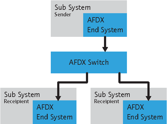
But how can one observe a system is functionally accurate as per the requirements and works effectively? Every system has its parameters defined to measure the performance and also to keep a check on the system’s design as per the specifications. The AFDX® data network based on the ARINC 664 part 7 protocol has its end system parameters described below. The below figure shows the topology view of the AFDX® protocol.
Virtual Link Management
AFDX® specifications state the primary responsibility of the Virtual Links (VLs) is the management of the transmission and receipt of data. A maximum of 128 VLs can be handled by an end system and can be configured for any desired configuration, such as transmitting four VLs and receiving six VLs, with three sub-VLs consisting of one receiving VL. For each VL and sub-VL, the end system maintains a FIFO queue.

As per one of Xilinx’s application note on ARINC 664 p7, the end system responsibilities are as follows:
At the Tx end;
- Reading each VL queue and incrementing the VL frame sequence number.
- Scheduling each frame for transmission to maintain the bandwidth guarantee within the allowed jitter.
- Transmitting redundant frames on both controllers A and B.
At the Rx end;
- Deleting redundant frames and policing ordinal integrity.
- Separating data by VL and writing received frames to the appropriate queue.
Bandwidth Control
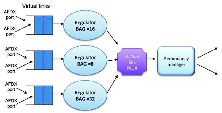
Toshiba mentions in one of its white papers, the ‘always on/connected cars” are emphasizing to increase the available bandwidth for in-vehicle data communications and the latest semiconductor technologies are helping in building solutions to cater to the system demands. Thus one can certainly consider that bandwidth comes out as a crucial design parameter. Between the frame payload and the frame transmission interval, the control mechanism for bandwidth varies. A transmission time slot is effectively allocated to each VL, within an assigned bandwidth allocation gap, a VL will transmit a frame.
Bandwidth Allocation Gap (BAG): This is the maximum rate of data that can be transmitted and it is guaranteed to be sent at that interval. When setting the BAG rate for each VL, care must be taken so that there will be ample bandwidth for other VLs and the total speed should not exceed 100 Mbit/s. Concerning time, it represents the minimum interval of time for a given VL between the beginning of consecutive frames. BAG has a range of a minimum of 1ms to a maximum of 128ms. The figure below displays the structure of the AFDX® packet scheduler.
BAG Size = 2k, where k is an integer with a range from 0 to 7
Jitter
When transmitting frames through the traffic shaping function, Jitter can be introduced. As synchronous frames are transmitted from distinct VLs, this jitter enables versatility for the end system. Jitter is defined as the time measured at the transmitting end system between the start of the bandwidth allocation gap interval and the first bit of the frame to be transmitted at that bandwidth allocation gap interval. The specification allows for 40 μs of jitter plus a number based on the bandwidth requirements of the VLs, limited to a maximum of 500 μs as a result of transmission technology.
Jitter (MAX) (µs) = Jitter(MAX ) ≤ 40+{[∑(∈(set of VLs)) (20+LMAX)✕8] ∕ NBW}
NBW: medium bandwidth (bps)
LMAX: maximum allowed frame size for the VL (bytes)
The figure below shows the jitter effect in AFDX

Latency
The system-wide latency is not specified in the ARINC 664, part 7 but It does allow some limits at the switch level and end system.
- For an End System: The standard limits the latency during the reception to less than 150 μs.
LatencyMAX (framep) ≤ p ✕BAG + JitterMAX + technological_latency_in_transmission
where, p is the number of the frame in a sequence of a data burst or fragmented data. For a single frame with evenly spaced data, p = 1.
- For a Switch: The latency for the switch is defined by the standard as the time elapsed before the last bit of the frame is transmitted before receiving the last bit of the frame. The latency of the switch consists of three parts: the technical latency of the switching function, the latency of the configuration due to the loading of the switch, and the time taken for the frame to be transmitted through the medium.
Defining the End System Capacity
The specification sets no limit on the number of VLs an end system can support and states that it must be feasible for an end system to transmit at the maximum frame rate of the medium. Nevertheless, for each VL, the end device must comply with bandwidth limits and LMAX values as well as acknowledge the total VL limit at the switch. Limits on the number of VLs to be supported by an end system must be set by the system integrator. The below worst and best-case scenario stats are based on a unit analysis only and are taken from one of the Xilinx specifications document for ARINC 664 part 7.
- The worst-case (minimum) number of VLs exists when the LMAX is 1,518 bytes for each VL and the maximum bandwidth (bandwidth allocation distance = 1 ms) is allocated to each VL. At 100 Mb/s, it takes 123.04 μs to relay a frame of this size (1,518 bytes + 20 bytes overhead).
- The best-case (maximum) number of VLs exists without considering limitations at the switch stage when LMAX is 64 bytes for each VL, and a minimum bandwidth (bandwidth allocation distance = 128 ms) is allocated to each VL. At 100 Mb/s, it takes 6.72 μs to transfer a frame of this size (64 bytes + 20 bytes overhead).
Redundancy Management
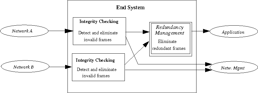
An AFDX network is designed such that there are 2 distinct paths between each ES (including MACs, PHYs, and cabling), as well as redundant switches to protect the network from a failure at or below the MAC level.
During transmission, the end system must simply transfer redundant frames via both controllers, unless needed by the VL. The specification states that redundant frames must be sent to each other within 0.5 ms.
During receipt, the end system must first verify the integrity of each incoming frame on both channels in parallel. The Integrity Checker must verify that the frame received has the expected sequence number for its VL, the previous sequence number (PSN) received plus either one or two, for each received frame passed from the MAC. The receiving end system is shown in the below figure.
When the Integrity Checker detects an invalid frame, the frame is dropped and the system is notified about the error. The effect of this check allows a single dropped frame in the data stream. For AFDX, a duplicate/redundant frame is defined as a frame received with a specified time window with the same VL sequence number as the last frame passed by the Redundancy Manager (for that VL) (defined by the standard as Skew MAX ).
A redundant frame is obtained after Skew MAX is detected and transferred to the partition as a new frame. Thus as NASA states in one of its research papers published on Communications for Integrated Modular Avionics (IMA), AFDX relies on the distribution mechanism of the MAC frame, using BAG to limit network bandwidth and Sequence Number to maintain the integrity of data.
Now as you advance on to make new IP designs based on the AFDX® protocol, do keep all your critical parameters in check. As I end this article here, I would like to mention a few things about our interactive team. We as a company design and develop systems that perform efficiently and are reliable. Just because we observe and accurately check all the parameters described in the specifications which makes our designs stand a class apart in the global platform for themselves and also our time and efforts invested in them.
So when you prefer to get solutions to your critical projects and build some reliable and secure systems in the age of next-gen technology, I would say, just give a missed call to this number +91 1244117090 , and we will connect with you within 48 hours. Haha, that sounds like some advertisement on the TV/Radio. Yes, you can do this also, but I would ask you to contact us if you prefer some premium standard products. Okay, that’s it, folks, signing off this time and will see you soon. Till then, stay connected with me in this era of the 5G world.