The ARINC 429 standard and Specification defines basic requirements for the transmission of digital data between commercial avionics systems. For ease of design implementation and data communications, signal levels, timing, and protocol characteristics are specified.
ARINC 429 is designed to provide the interchangeability and interface of commercial aircraft Line Replaceable Units (LRUs). As in a layman’s term, ARINC protocol is designed to support communication in the Local Area Network (LAN) of the avionics.
ARINC 429 is also known as the Mark 33 Digital Information Transfer System (DITS) bus. Although used mostly in the field of avionics, these buses are also used in the field of ground vehicles, weapons systems, and other commercial and military equipment.

The word structure, the electrical component characteristics, and the protocol needed for the requirement of successful communication is defined in the specifications. The Simplex, twisted shielded pair data bus standard Mark 33 DITS bus is used by ARINC 429. Both the hardware and data formats needed for bus transmission are specified by ARINC
A single connected transmitter or source consists of the hardware connected to from 1-20 receivers or sinks on one twisted wire pair. Data can only be transmitted in one direction (unidirectional connection), for bi-directional communication, it requires two channels or buses.
In a star or bus-drop topology, the modules, line replaceable units or LRUs, are most commonly configured. Multiple transmitters and receivers communicating on separate buses can be present in each LRU. Figure 1 shows the preferred connection topologies for the data bus. This simple architecture provides a highly efficient transfer of data, almost node-to-node connectivity.
A transmitter can only talk to a number of bus receivers, up to 20 on a single wire pair, with each receiver monitoring the related data continuously, but not accepting data reception. When large quantities of data have been transmitted, a transmitter can require acknowledgment from a receiver.
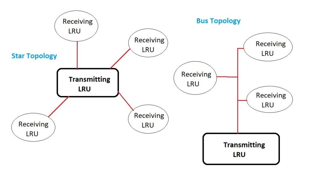
Figure 1. Preferred connection topology
As compared to a hard-wired handshake, this handshaking is done using a specific word style. Two twisted pairs comprising two channels are sufficient to carry information back and forth, one for each direction when this two-way communication format is needed.
Read More: ARINC 818 IP CORE
The transmission of the LRU source consists of 32-bit words containing a portion of 24-bit data containing the actual data and an 8-bit label describing the data itself. LRUs do not have an address assigned by ARINC 429, but rather an equipment ID numbers that allow device management and file transfer of equipment to be grouped into systems.
A null or zero voltage of at least 4 bits distinguishes sequential words. By using this null interval between words, a separate clock signal is unnecessary. That’s why this signal is known as a self-clocking signal. Transmission rates can be either at a low speed of 12.5 kHz or a high speed of 100 kHz.
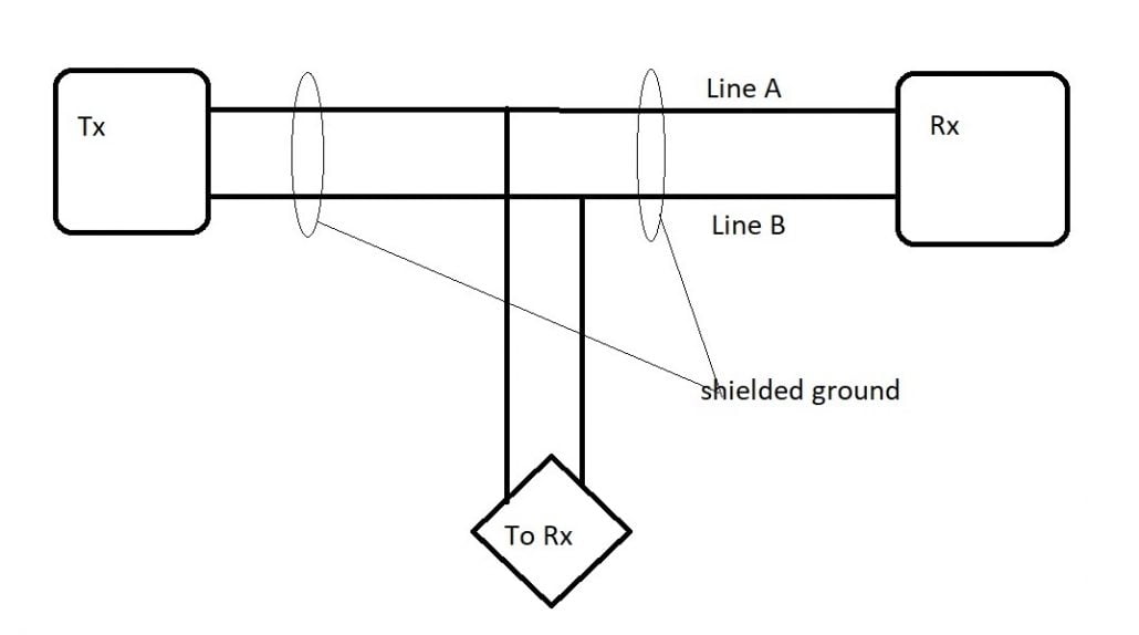
Figure 2. Cable attributes
For the transfer bus media, a 78 x shielded twisted pair cable is used. The shield needs to be grounded at either end and all junctions along the bus. The transmitting source output impedance should be 75Ω ± 5Ω equally split between Line A and Line B.
This balanced output should closely match the cable impedance. There must be a minimum effective input impedance of 8k x for the receiving sink. There is no definition of the maximum length, as it depends on the number of sink receivers, the drain of the sink, and the source power.
Most systems are designed for less than 150 feet, but if conditions permit, they can be extended up to 300 feet and beyond. Fig 2 shows the cable attributes for the ARINC 429.
Word Format
ARINC 429 assigns the first 8 bits as the wordmark, bits 9 and 10 are the Source-Destination Indicator (SDI), bits 11 through to 28 provide data information, bits 29 through to 31 are the Sign-Status Matrix (SSM), and bit 32 is a Parity Bit.
ARINC 429 standard data words are 32-bit words made up of five primary fields:
• Parity – 1-bit
ARINC uses odd parity as an error check to ensure precise data reception. The number of transmitted Logic 1s in each word is an odd number, with bit 32 set or cleared to get the odd count. ARINC 429 specifies no method of error correction, only error detection.
• Sign/Status Matrix (SSM) – 2-bits
Depending on the word Label, which indicates the form of data is being transmitted, the SSM field may provide different information. This field can be used to view the word information’s sign or location or to report the operating status of the source system and is dependent on the data type.
| Bit 31 | Bit 30 | Status (BCD) |
| 0 | 0 | Plus, North, East, Right, To, Above |
| 0 | 1 | No Computed Data (NCD) |
| 1 | 0 | Functional Test (FT) |
| 1 | 1 | Minus, South, West, Left, From, Below |
Table 1. SSM for BCD format
| Bit 31 | Bit 30 | Status (BNR) |
| 0 | 0 | Failure Warning |
| 0 | 1 | No Computed Data (NCD) |
| 1 | 0 | Functional Test (FT) |
| 1 | 1 | Normal Operation |
Table 2. SSM for BNR format
• Data – 19-bits
ARINC 429 identifies bits 11-29 as those which contain the data information for the word. The data pieces, indeed the entire word of ARINC 429, can be formatted very flexibly. When the data words are transmitted on the ARINC bus, the mark is transmitted first, MSB first, followed by the remainder of the bit field, LSB first.
• Source/Destination Identifier (SDI) – 2-bits
Bits 9-10 are used by the Source/Destination Identifier-SDI-and are optional under the ARINC 429 specification. To determine the receiver, the data is intended for the SDI may be used to identify the source that transmits the data or by several receivers. Instead of using them as an SDI sector, bits 9-10 can be used for higher resolution data.
The SDI is interpreted as an extension to the term Label when used as an identifier.
• Label – 8-bits
The mark is used to define the word’s data type (BNR, BCD, Discrete, etc.) and may contain instructional or data reporting information. Labels can be further refined by using the first 3-bits of the data field, Bits 11-13, as an Equipment Identifier to identify the bus transmission source. Equipment IDs are expressed in hexadecimal form as values.
In an ARINC transmission, the label is always sent first and is a necessary sector, as is the parity bit. Labels are first transmitted by MSB, followed by the remainder of the ARINC phrase, first transmitted by LSB.
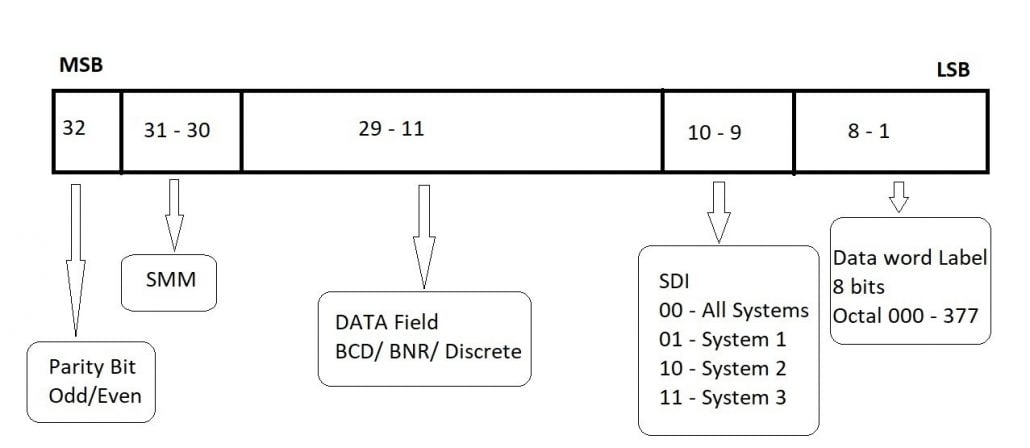
Figure 3. Word format of ARINC 429
Data Types specified in ARINC 429:
- Binary Coded Decimal (BCD):
The advantage of the Binary Coded Decimal technique is that each decimal digit is represented in the same way as Hexadecimal by a group of 4 binary digits/bits. So, for 10 decimal digits, we need a four-bit binary code (0-to-9). For displaying every decimal digit, the BCD format uses four bits of the data field.
To provide 5 binary values, up to 5 sub-fields can be used, with only 3 data field bits in the most significant sub-field. Bits 27-29 are padded with zeros if the Most Significant Digit is greater than 7 and the second sub-field becomes the Most Significant Digit, enabling the representation of 4 binary values instead of 5. The SSM field represents the sign of the data. - Binary Number Representation (BNR):
The fractional complement of the binary two. BNR coding stores information as a binary number. The sign of the data is stated with the bit 29, and a 1 indicates a negative number. MSB of the data is given by the bit 28. - Discrete Data:
It can be a combination of BNR, BCD, or ISO #5 bits. By setting or clearing predefined bits in the word data field, Pass/Fail, Activated/Non-Activated, and True/False conditions relating to device or subsystem operational activity can be described. - Maintenance Data / Acknowledge:
Maintenance details and acknowledgment means duplex or two-way communication between source and sink. For the LRU to send and receive data, two ARINC channels are required, because ARINC 429 provides for single-way simplex transmission only. Maintenance messages typically involve the exchange of a series of messages and mostly use a bit-oriented protocol, such as the Williamsburg/Buckhorn protocol. - Williamsburg/Buckhorn Protocol:
A bit-oriented protocol used to transfer files on the ARINC Data bus. If we require to transmit data more than 21 bits, file transfer protocol becomes a necessary and important factor. Source and sink units need to first create a handshake when initializing a file transfer with the bit-oriented protocol to decide a standard protocol that can be used by both the transmitter and the receiver.
A Word Send Request (RTS) containing a destination code and word count is transmitted. To ensure accuracy, the receiver responds with a Clear to Send word (CTS), re-transmitting back the destination and word count information. Upon verified receipt of the CTS files, the file transfer begins with the source.

Applications of ARINC 429 standard and Extending to other ARINC standards:
High reliability and small data rates at the cost of wire weight are provided by the unidirectional ARINC 429 network. In the early 1980s, the ARINC 429 was first used on the Airbus A-310 and the Boeing B-757 and B-767 aircraft.
In the 21st century, modern airplane designs continue to use the ARINC 429 bus for data transmission. The relative simplicity and integrity of the bus, as well as the ease of certification, are features that contribute to the continued selection of ARINC 429 buses when the required data bandwidth is not critical.
Military aircraft typically use a high-speed, bi-directional protocol specified in the Military Specifications of MIL-STD-1553. The interface DNx-429-516 ARINC-429 of United Electronic Industries (UEI) is intended for use with the company’s UEI Cube and RACKtangle chassis.
It is compatible with the commercial aviation ARINC-429 data format. Few other manufacturers have developed ARINC 429 based devices such as the North Atlantic Industries offers the AR429/575 module and a broad range of ARINC-429 Interface boards is provided by Alta Data Technologies.
One particular item is the PMC-A429HD, which provides RX and TX ARINC-429 channels with 16, 32, or 48 channels. Interface cards such as USB 429, OmniBusBox II, OmniBus II PCIe, AB3000, and MX5 series for a range of computer platforms, box products as controllers or connected via USB or Ethernet, and related software tools are included in the Ballard ARINC 429 products from Astronics Corporation. A newer system is installed on the 777 listed as ARINC 629 by Boeing, and some aircraft are using alternative systems to try and reduce the necessary wire weight and exchange data at a higher rate than is possible with ARINC 429.
Bell Helicopters, Boeing 727, 737, 747, 757, and 767, and McDonnell Douglas MD-11 are equipped with ARINC 429, the majority of which are commercial transports, such as aircraft A310/A320 and A330/A340.
You might be interested to read other valuable article on ARINC 818 – 3 : Take a step ahead with an upgrade to ARINC 818 Revision 3 Avionics Digital Video Bus
Learn About: Radar Data Acquistion system [RDA]
Do you have any query regarding ARINC 429 or 818, you can contact us directly.