The initial publication of the MIL-STD-1553 standard was for the U.S. Air Force in 1973 and was first used on the F-16 Falcon fighter aircraft. Other aircraft designs, including the F/A-18 Hornet, AH-64 Apache, P-3C Orion, F-15 Eagle, and F-20 Tigershark, quickly followed. But what is MIL-STD-1553
MIL-STD-1553 is a military standard for the U.S. Department of Defense that specifies the mechanical, electrical, and operational characteristics of a serial data transmission bus.
It is now widely used in avionics, aviation, and spacecraft data processing for the military as well as civil purposes. MIL-STD-1553 is the military counterpart of ARINC-429, even though it is somewhat different structurally.
Although commercial aircraft usually do not get wires cut by bullets or flakes, military aircraft are typically designed to not cause a loss of machine control by a single cut wire or wiring harness.
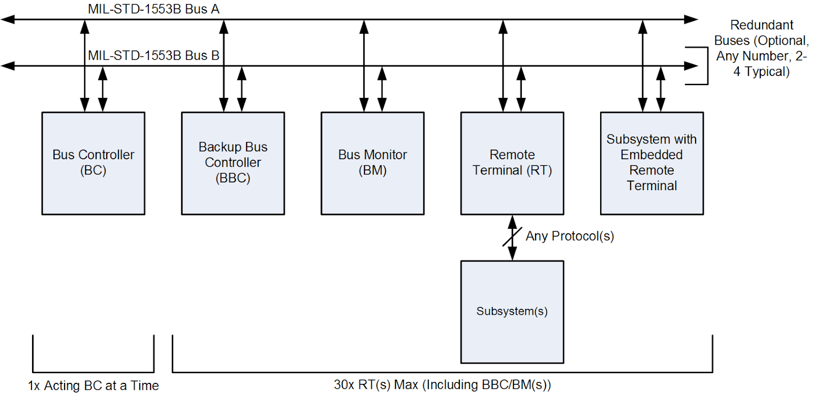
The MIL-STD-1553 usually uses a dual redundant physical layer with time-division multiplexing, half-duplexing, protocol differential network interface for command/reposition data exchange, which has up to 32 remote terminal computers.
It was adopted as STANAG 3838 AVS by NATO outside of the US. STANAG 3838 is used on the Panavia Tornado in the form of UK MoD Def-Stan 00-18 Part 2, BAE Systems Hawk (Mk 100 and later), and extensively on the Eurofighter Typhoon along with STANAG 3910-‘EFABus.’

In 1978, MIL-STD-1553B, which superseded the previous MIL-STD-1553A specification of 1975, was released. The fundamental difference between revisions 1553A and 1553B is that the options are specified in the latter rather than left to the consumer to identify as needed. It is the responsibility of the Society of Automotive Engineers (SAE) to provide repairs and any potential improvements to the standard. The MIL-STB1553B Note 2 format is employed by most modern systems. The last revision is MIL-STD-1553C made in February 2018. Let’s now dive into a brief discussion of the features and architecture of the bus.
Bus Protocol
There are one or more 16-bit words in all 1553 messages on the bus, categorized as order, info, or status word forms. Each term is accompanied by a sync pulse of 3 μs and followed by an odd bit of parity. Notice that since the sync pulse can not occur in a Manchester code (1.5 μs low followed by 1.5 μs high), it is also special.
With no distance between words, the words in a message are transmitted, but a gap of 4 μs is introduced between successive messages. Within 4 to 12 μs, all devices must begin transmitting a response to a command. If they do not start transmitting within 14 μs, the command message is deemed not to have been received by them.
Physical layer
A single bus consists of a wire pair at 1 MHz with 70–85 Ω impedance. For the high (positive) Manchester bi-phase signal, when a circular connector is used, the center pin is used. Using a pair of insulation resistors and, optionally, a coupling transformer, transmitters and receivers coupled to the bus via insulation transformers, and stub connections branch off. This decreases the effect of a short circuit and guarantees that the aircraft does not conduct current through the bus.
By using several separate wire pairs, the bus can be made dual or triple redundant, and then all devices are connected to all buses. In the event of a malfunction by the current master controller, there is a provision to appoint a new bus control computer.
The bit rate (1 bit per μs) is 1.0 megabits per second. The combined bit rate accuracy and long-term stability are only defined to be within ±0.1 percent, the stability of the short-term clock must be within ±0.01 percent. A transmitter’s peak-to-peak output voltage is 18–27 V. Optical fiber, which weighs less and has greater resistance to electromagnetic interference, like an electromagnetic pulse (EMP), is used in a separate variant of the bus. This is referred to as MIL-STD-1773.
Word Formats
Within a standard structure, each word type has a particular format. The length of all words is 20 bits and the first three bits are a synchronization field that allows the decoding clock to re-synchronize at the start of each new phrase. There is information in the next 16 bits, in a format that varies with the type of term. The last bit in the word is a bit of parity, which for a single word is based on odd parity.
A single message is a transmission of, if defined, a command word, a status word, and data words. In the case of RT to RT transmission, two command words, two status words, and data words are included in the message. The figure below describes the word formats used in the bus protocol.
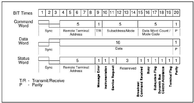
Command word: A Command Word format uses the first 5 bits of the Remote Terminal address (0 to 31). The sixth bit would be 0 for receiving and 1 for transmitting. The subaddress/mode code bits are indicated by the next 5 bits. If this field is either 00000B or 11111B, the Mode Code Command is the command.
In the subsystem, all other bits direct the data to specific functions. The Word Count or Mode Code to be carried out is determined by the next 5 bits. If this field is 00000B or 1111B, the mode code to be executed is specified by the field. If it isn’t, the field determines the number of data words (depending on the T/R bit) be transmitted or received. The last bit is word parity. Only odd parity is used.
Data word: The data is transmitted in a message and is stored in a data phrase. Data sync is used in the first 3 bit times, which is opposite to that used for a command or status phrase. Data words can be sent either through a remote terminal (transmit command) or through a bus controller (receive command). The reference point would be the remote terminal.
However, the designer needs the next 16 bits to be included. The only standard requirement is that first, it is appropriate to transmit the most important bit. The last bit is an odd parity bit.
Status word: By transmitting a status word, a remote terminal answers to a valid message. The status word informs the bus controller whether a message has been received correctly or not and what the terminal’s condition is. After receiving a correct command phrase, the status word is deleted. The bits are set again after the status word is cleared if the conditions that set the bits initially still apply.
If the data detects an error, the Message Error bit is set and the status word transmission is suppressed. Any time a broadcast message is received, the transmission of the status word is also suppressed.
Bus Controller
The terminal assigned the task of initiating information transfers on the data bus. There can only be one bus controller operating at a given time. There can be three types of Bus Controllers as described in the below table:
| Bus Controller | Function |
| Word Controller | Process 1 word at a time; hardly used in the recent years |
| Message Controller | Process 1 message at a time; communicate with the device when a message is complete or an error occurs. |
| Frame Controller | Process multiple message defined sequentially; interrupts the device only when the message stream is completed or an error has been found |
Bus Monitor
A Bus Monitor (BM) doesn’t send data over the data bus. Its primary purpose is to track and record bus transactions without interfering with the Bus Controller or the Remote Terminal’s (RT) operations. These bus transactions can then be saved for off-line review later. A bus monitor can be configured to record particular subsets of the bus’s messages. It can also be programmed as a backup bus controller, ready to take over in the event of a malfunction. The figure below shows a block diagram of the Mil-STD-1553B BC/RT/MT with PCI interface IP Core for a FPGA.
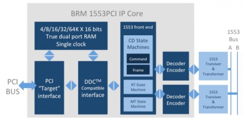
While the data rates of 1 Mbps may appear to be pedestrianized in the world, modern aircraft are yet to meet many data communication needs with more than sufficient 1 Mbps. The MIL-STD-1553B cores in conjunction with FPGAs are the flexible solution for integration into smaller, lower power, smaller weight, and more reliable systems on a chip of discrete circuits and long lead ASICs.
MIL-STD-1553B has advanced and is widely used in non-industrial, space-based applications to become the prevalent, globally recognized data bus standard for many military platforms. The Air Force, Navy, Army, and space agencies of nations around the globe have adopted MIL-STD1553B. Platforms other than aircraft that use 1553 include, to name a few, tanks, warships, missiles, satellites, and the International Space Station. 1553 is also used in many field-based support roles, such as test equipment, equipment for ground support, simulators, and trainers. There are more to discuss on this topic such as the hardware characteristics, connectors, and tools used, etc, and will be covered in upcoming articles.