Camlink Interface
Channel Link consists of a driver and receiver pair. The driver accepts 28 single-ended data signals and a single-ended clock. The data is serialized 7:1, and the four data streams and a dedicated clock are driven over five LVDS pairs. The receiver accepts the four LVDS data streams and LVDS clock, and then drives the 28 bits and a clock to the board.
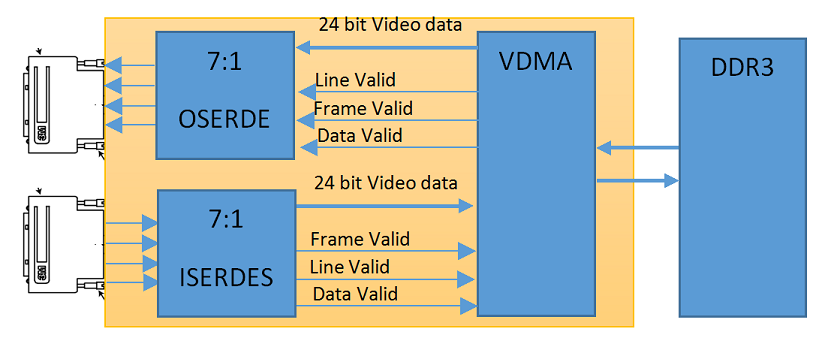
Logic-Fruit Cam-Link IP uses internal ISERDES/OSERDES modules to serialize/de-serialize the cam-link data. This help to save space on PCB by avoiding external serializer and de-serializer chips. Also this results in minimization of IO. Only 4×2 IOs are used instead of 28×2 IOs.
The Cam-link data has a maximum throughput of 85*24 = 2.04 Gbps. This data is stored/retrieved to a DDR3 memory through a specially design video DMA (VDMA). Other read/write ports can be instantiated in VDMA to perform Video Processing.


![Advanced Driver Assistance System [ADAS] Everything You Needs to Know](https://www.logic-fruit.com/wp-content/uploads/2022/10/Advanced-driver-assistance-systems-Thumbnail.jpg)